| Difficult | Execution Time | Data Analysis | Radioactive Sources |
|---|---|---|---|
  |
  |
Yes | No |
Purpose of the experiment
This experiment shows two ways to blink an LED on the DT1260 with Sci-Compiler: a counter–comparator design and a PWM-based design. The aim is to compare implementation effort and timing control while obtaining the same visual result.
Fundamentals
Digital systems often use periodic signals to control timing and sequencing operations. A blinking LED is a simple way to visualize a square-wave signal generated by a digital circuit.
The frequency of the blinking corresponds to the signal period, while the proportion of time the LED stays on defines the duty cycle. In digital hardware, such timing can be created either by manually counting clock cycles or by using a built-in Pulse-Width Modulation (PWM) generator.
This experiment demonstrates how essential concepts in digital electronics, such as timing control, signal generation, and logic synchronization, can be implemented and observed in practice.
Carrying out the experiment
Activate your Sci-Compiler license and set up the software installation. Plug the USB Dongle in your PC and launch Sci-Compiler. Create a project for your DT1260 unit: press New Project.
- Counter Method: Use a Chrono block to count clock cycles; two GREATER comparators set/reset an SR Flip‑Flop. Drive LED_0 with FF output; optionally drive LED_1 with the inverted signal.
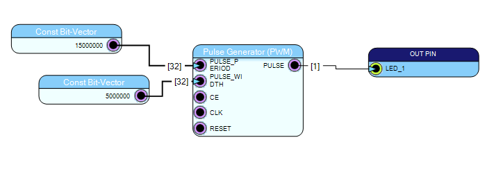
- PWM Method: Use a Pulse Generator (PWM). Set PERIOD and WIDTH constants; connect the PULSE output to LED_1.
Run & Observe: Build, program the DT1260, and verify blink frequency/duty by changing constants.
Results
Both approaches produce a stable blink. The counter method offers granular control over timing sequences; the PWM method minimizes design effort. Adjusting the constants directly sets blink frequency and duty cycle.
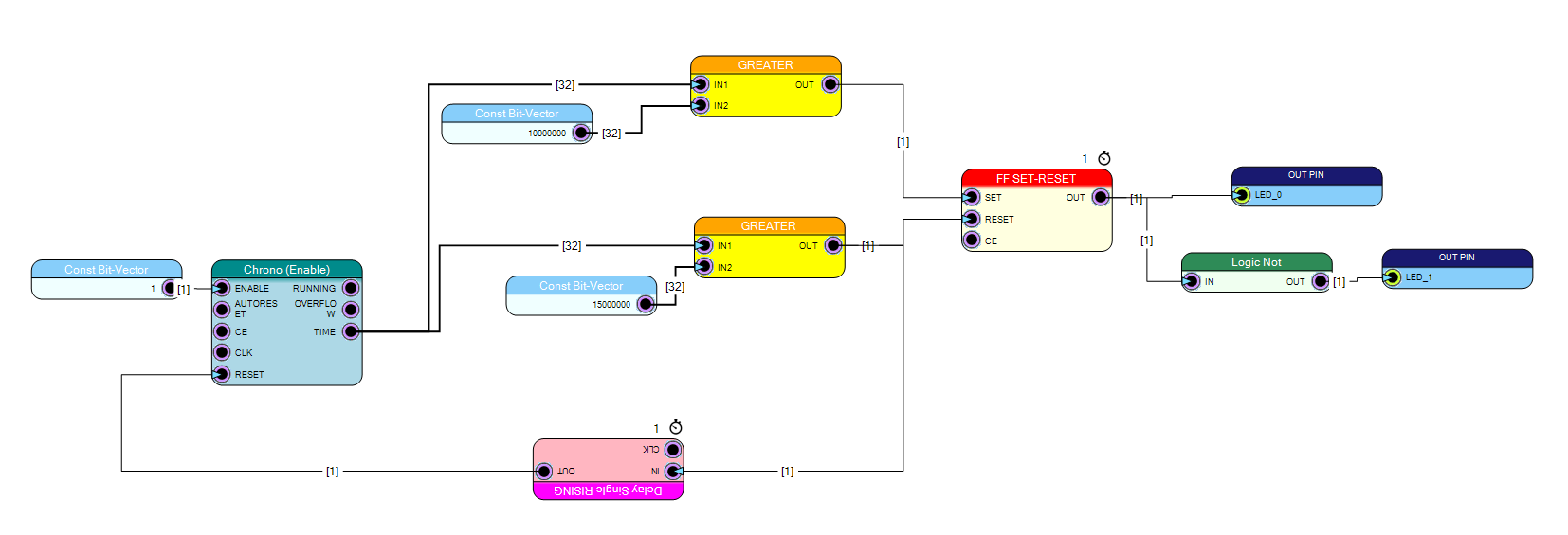
Low-Level Counter Approach.