| Difficult | Execution Time | Data Analysis | Radioactive Sources |
|---|---|---|---|
  |
  |
Yes | No |
Purpose of the experiment
The aim of this experiment is to demonstrate how event counting can be performed within a fixed time interval (dwell time) using FPGA logic. Students learn how to implement a timing-controlled acquisition that counts the number of detected events during a defined measurement period.
Fundamentals
In many measurement systems, event counting must be performed over a well-defined time interval to determine quantities such as event rate or signal intensity. This time interval, often called dwell time, defines the duration of the counting window. During this period, incoming events are accumulated by a counter. At the end of the interval, the counter value represents the number of detected events.
Implementing the dwell time directly in the FPGA ensures precise timing control, since the measurement interval is generated by the hardware clock rather than by software timing.
Requirements
Python environment.
Carrying out the experiment
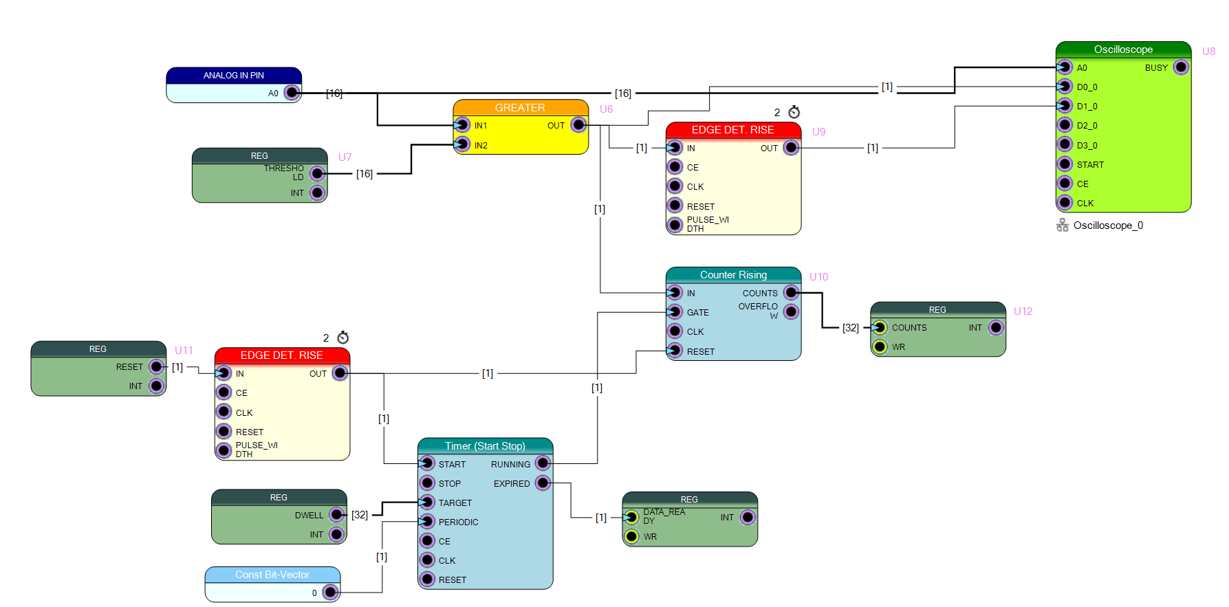
A firmware design is implemented including:
- an event counter that increments when a signal crosses the threshold,
- a timer block that defines the dwell time,
- registers used to control and monitor the acquisition.
After programming the DT1260 board, a signal source generates pulses at the input. The FPGA counts the events occurring during each dwell time interval. The results can then be read by the control software.
Results
The system counts the number of detected events within a fixed dwell time interval. By adjusting the dwell time or the input signal rate, students can observe how the number of counted events changes. This experiment illustrates how precise timing control implemented in FPGA hardware enables accurate event rate measurements in digital data acquisition systems.