| Difficult | Execution Time | Data Analysis | Radioactive Sources |
|---|---|---|---|
  |
  |
Yes | No |
Purpose of the experiment
The aim of this experiment is to demonstrate how the charge associated with a detector pulse can be measured using a digital integration algorithm implemented in FPGA firmware. Students learn how the area of a pulse can be computed to estimate the total charge generated by the detected signal.
Fundamentals
In many radiation and particle detection systems, the total charge collected from a pulse is proportional to the energy deposited in the detector. Instead of measuring only the peak amplitude, the signal can be analyzed by integrating the waveform over a defined time window.
In digital readout systems, the analog signal is first sampled by an Analog-to-Digital Converter (ADC). The charge is then estimated by summing the digital samples corresponding to the pulse over the selected integration interval. This process is known as charge integration.
Implementing the integration directly in the FPGA allows the system to compute the pulse charge in real time for each detected event.
Requirements
Python environment.
Carrying out the experiment
Activate your Sci-Compiler license and set up the software installation. Plug the USB Dongle in your PC and launch Sci-Compiler. Create a project for your DT1260 unit: press New Project. A firmware design is implemented including:
- a trigger block used to detect incoming pulses,
- an integration module that sums the samples of the waveform over a defined time window,
- registers used to store and read the computed charge value.
A signal generator provides pulses with controlled characteristics. The FPGA processes the incoming waveform and performs the charge integration for each detected event. The resulting values can then be accessed through the control software.
Results
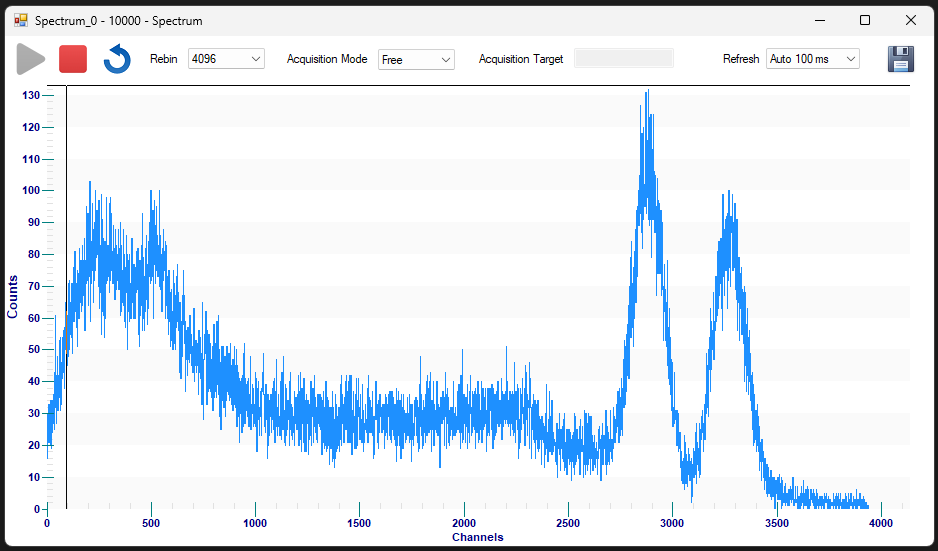
The system computes the integrated charge of each detected pulse by summing the waveform samples within the integration window. Students learn how the pulse area can be used as a digital estimate of the signal charge. By modifying the input signal amplitude or width, the corresponding changes in the measured charge values can be observed.